Digital Video and Field Order
This article was written in 2002, so some of the details may be a little out of date.
There is a certain amount of confusion in the world of desktop video editing over “Field Order”. Video newsgroups and bulletin boards attract a steady flow of queries about problems that people are experiencing with field order settings in their video projects.
Much of this confusion is caused by conflicting terminology: “upper-field-first”, “field order A”, “field 1”, “odd field” – and so on. Hardware and software manufacturers often give vague or ambiguous advice on this subject, leaving many users with a feeling that they just don’t know what is really going on, and why this should all be so complicated.
So I decided to get to the bottom of this. This involved going back to the standards for analogue video on which most digital video formats are derived and finding out how all of this confusion has arisen, and the correct definitions for many of these contradictory terms.
The standards themselves make fairly dry reading, but there are some interesting details there which help to explain the roots of digital video. If we understand some of this then it all becomes a lot clearer. So, I’ve extracted some of these details and presented them in a series of simple diagrams which help to explain, for example, why certain resolutions are used and the concept of the notorious rectangular pixels used in the video world.
The PAL television system runs at 25 frames a second. Each frame is comprised of 625 horizontal lines, and is made up of two interlaced fields separated in time by 1/50th of a second. If you number the lines from the top of the frame, the top line is 1 and the bottom line is 625. The first field contains the odd-numbered lines and the second field contains the even-numbered lines. But your’ll probably know most of this already, so I’ll move on to the more interesting stuff.
Although in desktop video we are dealing with digital video, the roots of digital video are firmly planted in the original analogue video standards. Most readers in the UK will be interested in PAL which has 625 horizontal lines, but we will also be describing NTSC which has 525 lines. In fact it’s more accurate to refer to 625-line and 525-line systems rather than “PAL” and “NTSC”, so that is what we will do in most of this article. We will start by describing the 625-line system because it has fewer complications.
Analogue and Digital Active Areas
OK, so let’s start with analogue video. “Interlaced” video is a continuous waveform comprising a stream of fields which are “shot” at a rate of 50 fields per second. But each field only contains the alternate lines in the original picture. The first field “field 1” contains the odd numbered lines (assuming that you start counting from 1 rather than 0), and the second field “field 2” contains the even numbered lines 1/50th of a second later – we will refer to these fields as “F1” and “F2” for brevity.
The analog waveform of a field carries a 'signature' that effectively identifies it as an F1 or F2 field. The signature occurs as a pattern of sync pulses that differs in F1 and F2 fields – this ensures that the lines of either field appear in the correct position on a traditional analog television screen. When these two fields are interlaced you end up with all of the lines in the picture making a complete “Frame”.
Each field has several lines that do not contain any picture information. These lines occur during the Vertical Blanking Interval (VBI) when the electron beam in the TV tube returns from the bottom to the top of the screen. The VBI also covers several lines which carry data such as Closed Captions and Teletext.
The lines which contain picture information comprise the “active” area of each field. The ITU-R BT.470-6 recommendation shows where the active picture area starts and ends in both fields. This is the analogue active area.
ITU-R BT.601-5 and 656-4 describe a digital active area. This is used when the analogue video signal is converted to a digital format, and it does not exactly coincide with the analogue active area.
The diagram below shows the analogue and digital active areas for a 625-line (PAL) system.
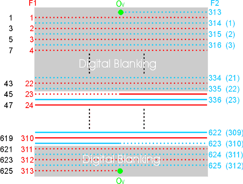
Diagram 1 - 625-line Analogue and Digital Active Areas
You can see how the two fields (F1 and F2) are interlaced together to make a frame. The frame-based line numbers are shown on the left in black – these range from 1 to 625 from the top to the bottom of a complete frame.
However, the ITU documents number the lines in temporal (i.e. chronological) order as they appear in the analogue waveform, so the lines of field 1 are numbered 1,2,3,4 and so on up to 313, and the lines of the subsequent field 2 are numbered 314,315,316 up to 625. The numbers in brackets show a different line numbering system used in some standards for field 2 which is 1 to 312.
The solid lines show the analogue active area. Note that it starts and ends with a half-line. The dotted lines show the Vertical Blanking Interval.
The digital active area is shown between the two grey Digital Blanking areas. The digital active area starts with line 23 of field 1 and ends with line 623 of field 2 – that's 576 lines in total. The first half of line 23 and the second half of line 623 are part of the (analogue) VBI and do not contain any picture data, but they are part of the digital active area all the same.
Converting the analogue video waveform to digital involves sampling the analogue waveform at regular intervals. ITU-R BT.601-5 states that both 525-line and 625-line systems are sampled at the same rate of 13.5 MHz - that’s 13.5 million samples per second. This common sampling rate is partly to keep equipment costs down.
Now, interlaced PAL has 25 frames per second, each with 625 lines. So the number of samples on a single line must be:
13500000 / 25 / 625 = 864 samples per line
And for NTSC which has 29.97 frames per sec, each with 525 lines:
13500000 / 29.97 / 525 = 858 samples per line
However, each line in the analogue video signal contains an area of horizontal blanking before and after the picture data which is used to keep the TV display synchronised. And we have already explained that each field contains several complete lines of blanking (the VBI) before and after the picture data. The sampling process is a continuous one which covers the whole video waveform including the horizontal and vertical blanking regions, not just the actual picture area. So we can represent a complete frame (of two interlaced fields) as an area of samples 625 lines in height by 864 samples in width, and within this is the window which contains the actual picture – the digital active area.
The process of digitally capturing the analogue signal involves storing only the samples which contain picture data - the samples from the horizontal and vertical blanking regions are usually ignored.
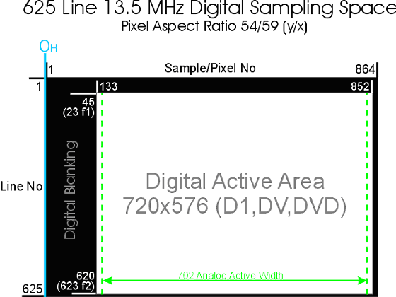
Diagram 2 - 625-line Digital Sampling Space at 13.5MHz
The ITU documents define the location of the Digital Active Area by specifying its first and last line number and the first and last sample number on the line. These numbers are shown on the diagram above. The area is therefore 720 samples wide and 576 lines high. This forms the image area which is stored in digital video files which is of course the well-known 720x576 pixels used in DV, DVD and other digital video formats.
OH is the location of the line sync pulse that marks the start of an analogue line. (For clarity on this diagram I have numbered the samples starting at 1 from the position of OH; however the ITU start numbering samples from 0 at the start of the Digital Active Area.)
Now, ITU-R BT.470-6 states that the active part of an analogue line (i.e the part of the analogue line which contains the picture) lasts for 52 microseconds. Using the 13.5 MHz sampling rate, this means that the width of the analogue active area only covers 702 samples. But the digital active area is wider, at 720 samples. Why the difference? Well, the extra 9 pixels on either side are to accommodate the growth and decay of the analogue waveform so that there is no abrupt clipping which may cause “ringing”. 720 also happens to be an exact multiple of 8 which helps in MPEG and DV encoding - but we won’t go into that here.
Some analogue video capture cards only capture 704 samples per line which is also an exact multiple of 8. However, many digital video standards specify 720 samples/pixels width. So if you have some video “footage” which is 704 pixels wide and you want to convert it to a 720 pixel wide format then you really need to add 8 black pixels to either side so that the correct proportions of objects in the picture are accurately preserved.
Rectangular Pixels
The analogue active area represents the area of the picture which can be displayed on a television screen. The aspect ratio of a TV picture is 4:3, that’s 4 units wide and 3 units high (for the sake of clarity we’ll leave out widescreen). We know that the picture has 576 lines, so we might think that its width in pixels should be
576 * 4 / 3 = 768 square pixels
but we know that the width of the analogue active area is just 702 samples (which are effectively pixels). Wouldn't 702 pixels make the picture too narrow? If that is the question you are asking then the problem is that you are thinking in terms of “square” pixels which are used in the computer graphics world.
Square pixels take up the same amount of space horizontally and vertically on a screen. For example, 1000 pixels across a computer screen takes up the same space on the screen (measured in inches, centimetres or any other spacial units) as 1000 pixels down the screen. A 500x500 pixel image will appear exactly square on a perfect computer screen.
But in the world of digital video we have rectangular pixels, and the width of the pixel arises from the sampling rate. As we said earlier, the length of the analogue active part of a line is fixed at 52 microseconds, and if we sample it at 13500000 times a second we end up with 702 samples covering the complete 52 microsecond time period. If instead we sampled at twice this rate, i.e. 27000000 times a second we would end up with twice the number of samples (1404) but they would be covering the same 52 microsecond period. We know that in 52 microseconds the electron beam must cover a particular distance across the TV screen, so we can see that there can be any number of samples across this distance depending on the sampling rate we choose. A higher sampling rate means more samples across the same screen width.
In digital video each sample is effectively a pixel, so the number of pixels across the screen width can vary depending on the sampling rate. So you can see that if we increase or decrease the sampling rate we are effectively squeezing or stretching the pixels horizontally so that in total they will occupy the same spacial distance across the screen.
ITU-R BT.470-6 states that the sampling rate is 13.5MHz, so at this rate the pixels turn out to be slightly wider than their height for 625-line systems. In fact the aspect ratio of this rectangular pixel is 54:59. Unfortunately the convention for stating the pixel aspect ratio is height:width (or y/x) which is the inverse of the convention for stating the frame aspect ratio (i.e. the aspect ratio of the picture) which is width:height (or x/y).
These rectangular pixels are often referred to as “Rec 601” pixels and they apply to D1, DV and DVD digital formats.
If we do a little maths on this we find that 576 lines comprising 702 of these rectangular pixels would make a picture with the frame aspect ratio of:
702 * 59 / 54 / 576 = 1.332
which is approximately our ideal 4:3 (1.33333) frame aspect ratio.
The diagram below compares the pixel aspect ratios of square (computer screen) pixels and the Rec 601 rectangular pixels for 625-line systems. It is based on the width of the digital active area which is 720 Rec 601 pixels wide. Note that 720x576 is spacially wider than the 4:3 frame aspect ratio, and corresponds to a width of 786.667 square pixels, i.e.:
720 * 59 / 54 = 786.667 square pixels
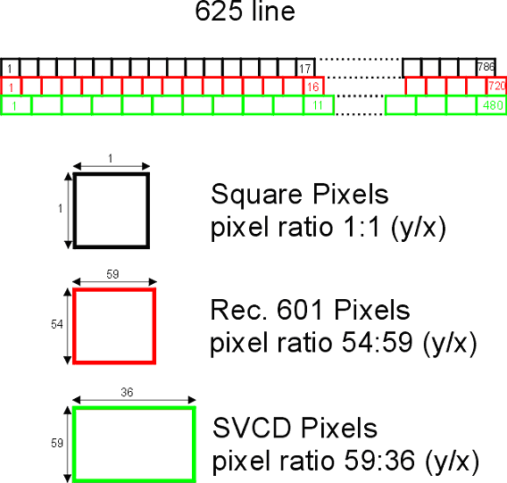
Diagram 3 - Pixel Aspect Ratios
The third type of pixels shown are for SVCD. SVCD stands for “Super Video Compact Disc” and is an official extension of the CD standard which can be used for storing interlaced digital video on standard compact discs. SVCD was popular with hobbyists before writeable DVDs became more affordable. Compact discs are relatively small for the use of digital video, so a much lower sampling rate is used. This results in only 480 pixels covering the same spacial width as the 720 Rec 601 pixels. SVCD pixels are therefore much wider.
525-line (NTSC) Systems
Let’s now look at the 525-line system used in NTSC. The diagram below shows the analogue and digital active lines for 525-line systems:
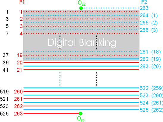
Diagram 4 - 525-line Analogue and Digital Active Areas
OE2 is the field sync pulse that marks the start of field 2.
The ITU standards show the analogue active picture area starting half way through line 282 of field 2 and ending half way through line 263 of field F1. However, over the years the FCC have allocated the first few of these lines to non-picture data such as line 20 and 283 carrying source identification data, and line 21 and 284 carrying closed caption and program rating information. Consequently the analogue active area is now specified by the FCC to start at line 22 of field 1, with all the preceding lines being part of the Vertical Blanking Interval (VBI). In addition, line 22 which is in the FCC’s visible picture area has been authorised to carry “electronic verification of television broadcasts” to track which programmes and adverts are actually aired.
The ITU's digital active area starts on line 20 of field F1 and ends on line 263 of field F1, which seems to give 487 digital lines, although the last line only has picture data in its first half. However, in practice one of these lines is dropped and only 486 lines form part of the digital active area – but which one? Chris Pirazzi in his excellent and oft-linked-to “Lurker’s Guide to Video” says that SGI hardware drops line 20 of field 1. However the working group of the ITU who are responsible for the ITU-R BT.656-4 document believe that line 263 should be omitted, perhaps because the start of the digital blanking period for field 2 can’t be on line 263, because this line begins in field 1!
Most digital formats such as DV, DVD and SVCD specify 480 lines as this is exactly divisible by 16 for MPEG encoding. This means that 6 lines must be dropped from the ITU’s 486 - but which 6? In practice this too seems to vary, but it would appear prudent to drop an even number of lines above and below to preserve the field order. Because the FCC specify that the (analogue) picture area starts on line 22, we could drop the four lines from line 20 of field 1 to 284 of field 2, and drop the remaining two lines from 262 of field 1. Or we could also drop line 22 of field 1 and 285 of field 2 and keep line 262 of field 1 and 525 of field 2. Some implementations do not even use a full 480 lines of picture data. Confusing, isn't it?
Nevertheless, the following diagram shows the ITU’s digital sampling space for 525-line systems.
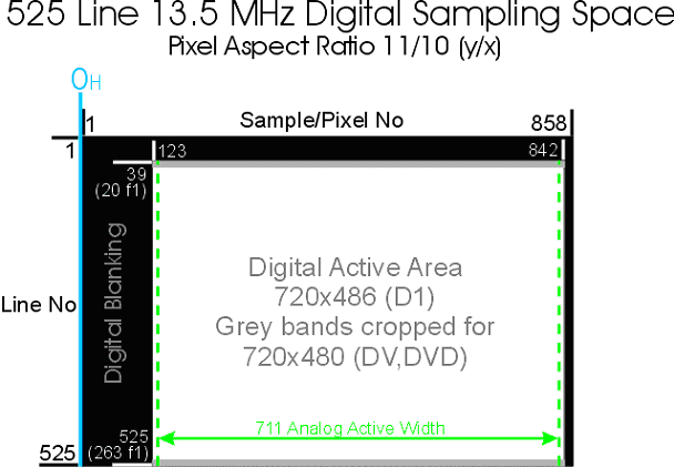
Diagram 5 - 525-line Digital Sampling Space at 13.5MHz
As shown earlier, the 525-line 29.94 frames per sec system sampled at 13.5 MHz gives 858 samples (Rec-601 rectangular pixels) per line. In this case the pixel aspect ratio is 11:10 which is narrower than the 625-line system’s 54:59, and also narrower than square pixels. Consequently the pixel aspect ratio of Rec-601 rectangular pixels for 525 and 625 line systems are not the same.
The ITU standards specify that the analogue active line length for M/NTSC (which is used in the US) is approximately 52.66 microseconds. At the 13.5MHz sampling rate this gives a width of the analogue active area of almost 711 samples.
So, 486 lines comprising 711 of these rectangular pixels would make a picture with the frame aspect ratio of:
711 * 10 / 11 / 486 = 1.330
which is roughly our ideal 4:3 (1.33333) frame ratio.
The diagram below compares the pixel aspect ratios of square (computer screen) pixels and the Rec-601 13.5MHz rectangular pixels for 525-line systems. It is based on the width of the digital active area which is 720 Rec-601 pixels. Note that 720x480 is spacially wider than the 4:3 frame aspect ratio, and corresponds to a width of 654.545 square pixels, i.e.:
720 * 10 / 11 = 654.545 square pixels
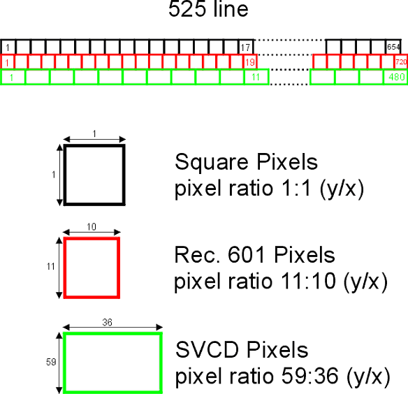
Diagram 6 - Pixel Aspect Ratios
Field Order
When two digital fields are interleaved we end up with a complete 576 line frame. The convention for referring to these two fields is the “upper” or “top” field (which contains the top line of the frame) and the “lower” or “bottom” field. Fields are 1/50th of a second apart, so if the upper field is temporally earlier than the lower field then we say that the field order is “upper field first”. If the lower field is temporally earlier than the upper field then the field order is “lower field first”.
In diagram 1 the top line (and alternate lines) of the digital active area is in F1. We know that F2 follows F1 so we might conclude that 625 line systems are “upper field first” – but this is not necessarily the case. It is not the video standard that defines the field order, it is the operation of the hardware used to capture and store the analogue video waveform.
Let’s assume that we have an analogue video capture card which complies with the ITU standards. It must therefore capture lines in the range 23 to 310 of field 1, and lines 336 to 623 of field 2. When these are interlaced to make a frame then line 23 is the top line. This means that the capture card (and its drivers) must slot F1 into the upper field and F2 into the lower field of the frame. But this still does not tell you whether the field order of the resulting frames is upper or lower field first.
Remember that the video waveform is a continuous stream of alternating F1-F2-F1-F2-F1 fields. If the capture card starts from an F1 field, then the F1 field is fed into the upper field, and the subsequent F2 field is fed into the lower field of the frame. In this case the field order is indeed upper field first. However, if the card starts instead from an F2 field, the F2 field is fed into the lower field and the subsequent F1 field is fed into the upper field of the frame. We now find that the field order is lower field first, because within the interlaced frame it is the lower field which is temporally earlier than the upper field.
The diagram below illustrates an analogue video waveform being digitised by a video capture card. It is of course vastly simplified. To make it easier to see what is going on, the picture carried by the waveform starts off completely white, and then fades quickly to black in just 5/50ths of a second. So the waveform begins with several “white” fields, and then 5 fields getting progressively darker, and then several “black” fields. The diagram shows an instant where this fade-out is being digitised. Each pair of fields are interlaced and stored in an AVI file as frames.
To make it easier to see what is happening, only the top 8 lines of each interlaced frame are shown. If you bear in mind that lighter greys occur “earlier” than darker greys, then you can easily see the field order of the interlaced frames in the AVI file.
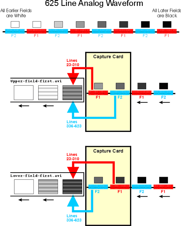
Diagram 7 - Field Order
Both of the capture cards shown are ITU compliant so they produce interlaced frames whose top line is line 23 of field F1. However, the first card processes field F1 first and then field F2; the second card processes field F2 first and then field F1. You can therefore see the results of digitising an F1 or an F2 field first.
However it is not uncommon for some hardware to start capturing on another line, for example the line 336 of field F2. In this case it is an F2 field that is fed into the upper field and not an F1 field. So now if the capture card starts from an F1 field, the F1 field is fed into the lower field, then the subsequent F2 field is fed into the upper field of the frame, and the field order is therefore lower field first – the opposite of the previous case.
So you can see that the field order of the frames in the captured AVI file depends on both the line number where capturing starts, and which field F1 or F2 is digitised first.
As a computer user, both of these things are usually hidden from you. If you are lucky the documentation for the capture card will tell you whether the card is upper or lower field first – i.e. the field order of the digital video files it creates. If not then you are completely in the dark and you must examine the files yourself to find out what their field order is – but you will only have to do this once as the card will always produce files with same field order (unless it has buggy drivers!).
Many video file formats do not carry information which tells programs the field-order of the interlaced video material they contain. Consequently you need to know the field-order of your video clips and tell the video applications what it is, although some programs will have a stab at trying to work out the field-order by analysing the picture content – but they can get it wrong!
The problem really arises when you have a video editing project on your PC that contains clips from multiple sources that have differing field orders, or you want to use another program perhaps to convert your video to another file format.
Changing the Field Order
Suppose your capture card generates AVI files that are upper field first and you cut to an AVI file which is lower field first. Now when this is output from your capture card to a TV monitor, the first clip will play fine as the fields will be output upper field first (which is the same order as the fields were originally captured); but the second clip will also be output upper field first which is the opposite order to which its fields were captured. The result is that when the playback reaches the second clip, motion will appear jerky because the fields are being displayed in the wrong order, effectively jig-zagging back and forth through time.
The solution is to change the field order of the second clip. This effectively shifts the frame boundary by 1 field. In this example, the new first frame will contain the upper field of the old first frame interlaced with the lower field of the old second frame; the new second frame will contain the upper field of the old second frame interlaced with the lower field of the old third frame, and so on. However, this would result in the old first field and old last field of the second clip being discarded, making the clip 2 fields shorter in duration.
An alternative would be to discard only the first field and duplicate the last lower field which would then be paired with the final upper field – this would cause a temporal discontinuity in the final frame of the clip but would maintain its duration.
For example, the field order can be changed in Premiere by selecting the clip in the timeline and changing its video properties by ticking both “reverse field dominance” and “interlace consecutive frames”. This uses the second solution above. Note that you must tick both of these options. “Reverse field dominance” just swaps the odd and even lines within each frame which is completely wrong as it effectively causes a vertical spacial “scrambling” of alternate lines. “Interlace consecutive frames” swaps the lower fields between each pair of frames, so that the new frame 1 contains the upper field of the old frame 1 interlaced with the lower field of the old frame 2, and the new frame 2 contains the upper field of the old frame 2 interlaced with the lower field of the old frame 1. The combination of these two options properly changes the field order of the clip.
An alternative (and simpler) solution is simply to shift all of the lines in the frame up or down in unison by 1 line. This effectively shifts all of the lines that are in the upper field to the lower field, and vice versa, but without causing any spacial scrambling. It does however mean that you lose 1 line of picture detail from the top or bottom of the frame.
Upper, Top, Odd, 1 or A ?!
And so we come to the source of so much confusion in the world of digital video: the naming conventions for fields and field ordering.
As we now know, an interlaced frame consists of two fields. One field contains the top line of the frame and all of the alternate lines beneath, and the other field contains the line-below-the-top-line and the alternate lines beneath. Notice that I have avoided using numbers in this description (such as line 1 or first line), and there is a reason for this which will become clear.
We need to give these two fields different names so that we can easily distinguish between them. There are several naming conventions used, but almost all of them are open to misinterpretation, and should therefore be avoided if at all possible.
The only names which seem to be unequivocal are “upper field” and “lower field” (or “top field” and “bottom field”). The upper field contains the top line of the frame and the lower field contains the line-below-the-top line of the frame. The meaning of the terms “upper” and “lower” become obvious if you just imagine the top two lines of a frame.
You can now also express the field order as “upper field first” or “lower field first” without fear of confusion. Consequently we will use the terms “upper field” and “lower field” as our naming convention.
Here are some of the other terms often used and why I think they should be avoided:
Odd Field and Even Field – If you look at the frame-based line numbers you can see that one field occupies the odd-numbered lines and the other field occupies all the even numbered lines. This seems like an ideal system for naming the fields, except that some specifications start numbering the lines from 0 instead of 1. So the “odd” field could be either the upper or lower field depending on how you start numbering the lines. Consequently the field order “odd field first” is not very helpful.
Field A and Field B – There is disagreement over whether Field A refers to the upper field or the lower field. And some programs such as TMPGEnc take “Field Order A” to mean upper field first, while others such as Ulead’s products take it to mean lower field first.
Field 1 and Field 2 – The analogue video waveform contains two types of field which have different sequences of sync pulses. These two fields are called in the ITU specs “field 1” and “field 2” and the video waveform alternates between the two which produces the interlaced picture on a TV screen. However as we have seen it does not necessarily follow that field 1 is the upper field. Depending on how the waveform is captured, field 2 may be the upper field. This may be further confused by some people simply assuming that field 1 must always mean the upper field or the earlier of the two fields in a frame.
Field Dominance
Field Dominance is not the same as Field Order, although it is often used as such. It has nothing to do with whether the upper or lower field is temporally earlier within a frame.
In the studio, analogue video is stored on tape as a series of alternating F1-F2-F1-F2-F1 fields – there are no frames as such. When this material is edited in the analogue editing suite, separate video clips must be joined together, but we must be careful to preserve the alternating F1-F2-F1-F2 sequence of fields across the “joins”. We must therefore decide whether a new scene begins on an F1 or F2 field, and provided we stick to that rule then the alternating sequence of fields will be correct for the complete edited tape. This “rule” is the Field Dominance.
If our scenes (i.e. our edits) start on field F1, then our editing system is F1 Dominant; and if the scenes start on field F2 then our system is F2 Dominant.
However, when this is digitised and transferred to our PC we no longer know which field was F1 or F2. All we see is our AVI file containing an upper and lower field, and we usually don’t know which was an F1 or F2 field in the original video waveform.
Similarly, computer-based video editing programs use the frame boundary for their editing “joins”. A cut from one scene to another occurs on a frame boundary. Because we know that these frames are either upper or lower field first then we could say that our video material is “upper field dominant” or “lower field dominant”. And some people do use these terms, although dominance is really meant to be applied to the F1 or F2 analogue fields.
Furthermore, if we are capturing some material which has the opposite field dominance to that of our capture card, we could end up with a clip which has scene changes in mid-frame. In this case we could have a clip with field order “upper field first” but with “lower field dominance”!
Some Digital File Formats
Lets conclude by taking a quick look at a couple of the common pro-sumer digital video formats and their field order.
Most video formats stored on computer do not contain any information about the field order of the video material they contain. This means that we usually have to study the file contents to work this out ourselves.
DV & DVCAM
DV & DVCAM is used in consumer and semi-professional camcorders. In 625-line systems it has a resolution of 720x576, and in 525-line systems is 720x480.
DV uses intra-frame compression, which means that each frame is compressed separately, so it is very easy to edit. It also makes it easy to start recording over material on the camcorder at any particular frame.
The DV standards say that the digital active area of DV for 625-line systems is from line 335 of field 2 to line 310 of field 1. If you take a look at diagram 1 you’ll notice that this range is offset from the ITU specs by 1 line.
Similarly the digital active area for 525-line systems is from line 285 of field 2 to line 262 of field 1.
Consequently in both systems field 1 is the “lower” field. Field 1 dominance effectively means that the field order of DV material is “lower field first” for both PAL and NTSC, which is nice!
DVD
DVD uses MPEG1 or MPEG2 compression, but only MPEG2 can store interlaced video.
MPEG uses inter-frame compression, which means that most frames are encoded by storing only the features in the image which have changed compared to previous (or later) frames. This makes it more difficult to edit because you usually have to build up a complete frame by accumulating the changes over several previous frames.
The MPEG specs say that interlaced material is encoded as a series of separate fields with each field identified as a “top” or “bottom” field. Alternatively it may be encoded as a series of frames containing two interlaced fields, and each frame has a flag which states whether it is “top field first”.
In either case the field order is effectively contained within the MPEG file. A DVD player would have to output the fields in the specified order.
References
Analogue and Digital TV:
Rec. ITU-R BT.470-6
Rec. ITU-R BT.601-5
Rec. ITU-R BT.656-4